Webmaster's Note
The great majority of this page, including the following paragraph, is from the 1955 edition of AFM 51-40. However, I've also included the portion of the 1960 edition that covers the MA-1 pendulum sextant and the MA-2 bubble sextant.
In order to perform celestial navigation, it is necessary to have some sort of device with which to determine the altitude of celestial bodies. That device is the sextant. The Air Force has several types of bubble sextants. Only the current models now in use will be discussed in this section. They are: the A-l0-A, the A-14/(AN 5851-1), the A-15, and the MS-2811 or, as it is commonly referred to, the periscopic sextant. Undoubtedly, there will be later improved models after this manual has been published.
The material in this section presents a description of the sextant together with procedures for operating and caring for the instrument.
The first sextant to be discussed is the A-l0-A.
The type A-10-A aircraft sextant is a precision instrument designed for use in aerial navigation. With this instrument, the angular altitude of a celestial body can be measured and recorded with reference to a bubble artificial horizon. This sextant is an indirect sighting instrument. This means that by looking in a horizontal direction and turning a prism geared to an altitude scale, it is possible to bring a celestial body into the field of view. With the body in collimation, the altitude is read from the altitude window. The A-10-A has an automatic marking device which is operated by a solenoid timing mechanism, which makes a mark on a plastic disk. This is a visual averaging mechanism. It is necessary to use the battery case at all times since it furrnishes power for the solenoid mechanism as well as bubble illumination. However, if the mechannism is inoperative, the marker may be operated manually without the use of the battery case and batteries.
The type A-10-A sextant utilizes three systems to obtain and record a celestial observation: The mechanical system, the optical system, and the electrical system.
The mechanical system coordinates the movement of the field prism with that of the counter and marking disk. This coordination is accomplished by means of a gear train.
The field prism revolves through an arc of 45° producing a nominal range of 90° plus an over run of 2° on either side of the extreme deflection. The field of vision encompasses 12°30′.
The control knob beneath the sextant moves the field prism by means of a series of gears.
The marking disk is made of plastic and is removable for easy replacement or cleaning. The plastic disks can be cleaned with an eraser, or soap and cold water, and can be used on both sides. The marking disk moves in conjunction with the field prism when the control knob is turned.
The counter displays the angular reading in degrees and minutes of arc.
Look at the illustration at the right. The movable field prism receives the rays of light from the body and transmits the rays to the fixed prism which in turn transmits them to the eyepiece for observation.
The objective lens in the eyepiece focuses the light rays for a clear image.
The reflector superimposes the bubble image on the celestial image within the field.
The electrical system consists of a power source made up of a pocket, three cell battery case and three standard 1.5 volt dry cells, size D. A small cable connects the case to the sextant via a small connection on the bottom of the sextant. Two small bulbs, Kollsman instrument lamp, type 71A, 3 volt DC are used to illuminate the bubble, the recording disk, and the counter. These bulbs are the same type used for illumination in many aircraft instruments. If necessary, you can replace a burned out bulb with a spare one from one of the instruments.
The timer, self-contained electric clock mechanism, is housed in the left side of the sextant. When you hold down the starter switch, the timer closes a circuit to a relay. This relay in turn operates a solenoid. The solenoid then actuates a marker assembly, which places a small pencil mark on the marking disk. The marker is tripped sixty times per minute. When the solenoid fails to operate automatically, it may be operated manually by pressing on the flat side of the marker.
The bubble light rheostat, which is situated on the left side of the sextant, controls the illumination of the bubble cell. Illumination of the recording disk and counter is controlled by a toggle switch underneath the timer mechanism housing.
The artificial horizon is supplied by a bubble of air in a chamber of alcohol. Instructions for regulation of the bubble size are etched on the bubble chamber. A hollow or doughnut shaped bubble is used and the body is observed through the center of the bubble.
Two filters of different intensities are positioned between the eyepiece and the fixed prism. Care must be taken during night observations that the filters are not in position. There is always a red faced observer who has complained that he could not see a star in the field only to find the filters were in position.
Sometimes when you are viewing a dim star, the star may seem to keep fading away. To assist you in observing dim stars, a telescope is included in each sextant kit. The telescope has a two power magnification and reduces the field of vision by approximately one half. Usually, it is necessary to reduce the bubble size when the telescope is attached.
The sextant is held in the right hand by grasping the recording disk housing. The middle or index finger of the right hand is used to operate the marker trigger.
The battery case may be inserted in a convenient pocket and the cable attached to the sextant.
The sextant should be hung in the astrodome. A hook is provided with each sextant. These hooks are so designed that when the sextant is hung on them and used for making observations, the effects of refraction from the astrodome are kept to a minimum. The hook also provides extra support which makes it easier to hold the sextant steady.
If the sextant is to be used to observe the sun, position the filters to best suit yourself. For star shots, be sure to turn up the bubble illumiination.
1. Use the left hand to operate the altitude knob and bring the celestial body into the field of view.
2. Collimate by placing the body in the center of the bubble.
3. Depress the trigger of the solenoid timing mechanism. As long as the trigger is held depressed, the timing mechanism is actuated and one mark is made on the disk every second.
4. Time the observation. The observation may be for any period of time and the middle (visual) value of several readings in a series is the average.
5. In determining the average, align the middle of the group under the marker and read the average altitude from the counter, in degrees and minutes.
6. If the observations have been equally spaced, a direct average can be obtained. If they are unequally spaced, you will have to make a visual interpolation. The illustration on the preceding page shows the selection of the average value for three different observations.
As mentioned previously in this manual, the sextant must also be checked to be sure that it is accurate. An inaccurate sextant can be worse than useless, it can be dangerous if you are not aware of the fact that the error exists.
The A-10-A should be checked for back lash error and index and collimation error. The simplest way you can check for back lash error is to fix the sextant in position and sight on some point or object. Note what the reading is to this object. Then, turn the control knob so that the prism is rotated to its highest extreme. Now, rotate the control knob and sight again on the same object. The second reading should be identical to the first. If the two readings differ, the difference is the amount of back lash error present in the sextant.
When you are checking for collimation and index error, you should use a collimator, if it is available, or prepare an Hc curve. Collimators and curves are discussed later in this section.
It is also a good idea to clean the prisms occasionally. Just like a window, it's much easier to see through a clean one. To clean the prisms, turn the control knob until the counter reads 00°. Then carefully snap off the shade by pushing up on it while slowly rocking it from side to side. Next turn the control knob until the counter reads 090°. Clean the field and fixed prisms with lens tissue or a well washed, clean handkerchief. When you are replacing the shade, insert it between the fixed prism and the head of the mounting screw before snapping it on.
Before going on to the next sextant, one more word of caution. Do not spin the control knob rapidly. Spinning the control knob rapidly exxerts a sudden force through the mechanism which may cause damage to the counter mechhanism. For additional information on the A-10-A sextant, refer to T. O. AN05-35-33.
The A-14 sextant is an indirect sighting sextant designed for horizontal vision. This sextant incorporates a chronometric averaging device which, at the end of a two minute sighting period, indicates the average altitude on a counter and base scale. The averaging mechanism picks off the values of the altitude setting at two second intervals and accumulates these values through a gear reduction on the counter. Recall that with the A-10-A sextant the average could be determined for any desired time interval. With the A-14, since a gear system is used to accomplish the averaging, you must enter a full complement of 60 observations and maintain collimation for a full two-minute period. If the collimation is stopped before the end of the two-minute period, the reading on the counter is worthless.
Again, recall that with the A-10-A, collimation of the body is accomplished by centering the bubble and turning the control knob so the body is viewed through the center of the bubble. With the A-l4, the body is viewed alongside of the bubble, the bubble in the A-14 is opaque. The A-14 also has an astigmatizing device. If you use the astigmatizer, the celestial body appears as a line of light and it is placed through the bubble. Portions of the line of light in this case will extend on either side of the bubble.
The discussion of the component parts of the A-14 sextant can be broken down generally into three topics: the optical system, the bubble chamber, and the averaging mechanism. For detailed descriptions of each integral part refer to T.O. 05-35-22.
The sextant assembly is fundamentally a telescope with the addition of four reflecting prisms: the eyepiece prism, the reflector prism, the movable horizon prism, and the rotatable index prism. A sight of a celestial body is obtained by means of reflection through the index prism. The image passes through the telescope objective lens to the reflector prism, and then to the eyepiece prism and finally to the telescope eyepiece lens. The bubble artificial horizon is formed in the bubble cell, which is placed between the reflector prism and the eyepiece prism. In this manner, the bubble and the reflected image of the body are viewed together.
A sight of the natural horizon may also be obtained. To sight using the natural horizon, you move the horizon lever which places the horizon prism in the optical path. Notice in the first part of the illustration on the opposite page that the horizon prism is not in the optical path. The horizon prism is situated so that the sighted image of the horizon and the body are made to coincide in the telescope objective lens. Then, as before, the images pass to the reflector prism, the eyepiece prism, and the telescope eyepiece lens.
As in the A-10-A, there is a shade glass assembly in the A-14 sextant. By rotating the shade glass disk on the side of the sextant, you can make your choice of one of four variously colored glass filters, or a blank opening. In addition, a polarizing filter is provided which slips into the eyepiece. If the sextant is to be used at night, it is a good idea to check to see that the polarizing filter is not interfering with your vision through the sextant.
As mentioned before, the A-14 sextant is also equipped with an astigmatizer lens assembly, and is used to change a point image into a narrow line. The assembly is operated by a lever which swings the astigmatizer in or out of the optical path. In elongating the image of the sun, a star, or the full moon to a band of light, the astigmatizer makes observations more accurate under certain conditions. Instead of requiring you to bring the true image of a celestial body to the same horizontal level as the bubble by placing the two side by side, the astigmatizer enables you to bisect the bubble with the line of sight.
Before leaving the optical system, there is one more thing that should be mentioned. The eyepiece itself can be focused by loosening the colllar which is holding it and sliding it in or out until the desired focus is reached.
The vapor bubble assembly consists of two chambers, a diaphragm chamber and a bubble chamber. These two chambers are connected through a small port. The size of the vapor bubble is controlled by the pressures applied to a flexible diaphragm in the diaphragm chamber. This pressure is applied when you press, or turn, the control. Directions for use of the control are printed on the sextant. Contrary to the A-l0-A sextant, it is not necessary to provide an outside source ot light for the bubble. The bubble in the A-14 sextant is illuminated by a ring of radioactive, luminous material which is painted on the edges of the bottom of the bubble chamber.
The averaging device assembly is a contributory mechanism used to obtain automatically the average reading for 60 sights on an observed celestial body during a two minute interval. The purpose of the averaging device is to reduce any error in the final mean reading, due to the uneven acceleration of the bubble in a moving aircraft, and to one or more inaccurate sights in a series. At the end of two minutes, the mechanism stops, throwing a shutter into the optical path of the sextant assembly. Basically, the averaging device consists of an averaging mechanism gear train, a spring driven clock mechanism, and a counter.
One other item worth mentioning before going into the operation of the sextant is the lighting assembly. The lighting assembly has two small electric bulbs which may be used to illuminate the counter reading and the stop watch. As with the A-10-A, the power is supplied by batteries carried in a battery case. A terminal on the bottom of the sextant supplies the connecting point. You will notice that there is quite a bit of difference in the operating procedure for the A-14 as compared to the A-l0-A sextant.
The operating instructions for the A-14 sextant appear on a plate which is riveted to the sextant. However, the procedure as written here is a little more complete.
1. Set the counter to zero by turning the counter knob. If the counter is not zeroed, the observation will be worthless.
2. Wind the averaging device until you reach a solid stop. This not only resets the averaging mechanism, but also removes the shutter from the field.
3. Push lever 2 and rotate the scale drum to a stop. This operation engages the sextant scale drum with the averaging device, and the stop indicates that the averager has been brought down to the base line.
4. Push lever 1 to engage lever 2. This operation disengages the averaging device from the sextant.
5. If precomputation techniques are being used, set the Hp in the sextant.
6. Take a preliminary sight. That is, collimate the body. Then push lever 2.
7. Again, rotate the drum down to a stop, and if the amount of rotation is more than 2° as indicated on the micrometer drum, rotate the drum up to the sighted angle and collimate the body.
8. If the amount of rotation down to the stop is less than 2°, disengage the averaging device by pushing lever 1, rotate the drum down approximately one full turn, push lever 2, and continue rotating the drum down to a stop. Then proceed with the sight.
There is always a 15° spread between stops, which allows at least a margin of 2° on either side of the altitude of the body. This allows sufficient spread of altitude during observation.
9. Push lever 3 to start the averaging mechanism.
10. Maintain coincidence between the bubble and the celestial body. At the end of two minutes, a shutter automatically moves into the field obscuring your vision.
11. To obtain the average time, add one minute to the starting time of the observation, or subtract one minute from the time you finish your observation.
12. To obtain the final average altitude, combine the counter reading with the main scale reading. (Do not read the scale drum; this indicates the altitude of the 60th shot only.) For example, if the counter reads 7°44′, and the main scale pointer is between 2 and 3, the final reading is 27°44′. Remember, the final main scale reading is within 2° of the average reading.
Like the A-l0-A, the A-14 sextant should also be checked for index and collimation error.
When checking for collimation and index error, you should use a collimator, if it is available, or prepare an Hc Curve. These are discussed later in this section.
With the A-14 sextant, you should also check the averaging device and timing mechanism. This may be done as follows:
1. Prepare the sextant as though you were going to make an observation.
2. Set the scale drum on zero.
3. Push lever three. At the same time, start a stop watch.
4. When the timing mechanism stops, stop the watch. It should have run two minutes, and the reading on the counter dial should be 0°00′. If either the timing or the counter are off an appreciable amount, turn the sextant in.
The A-15 sextant is a modification of the A-14 (AN 5851-1) and differs from the A-14 only in the averaging device. Recall that with the averaging device on the A-14 sextant it is necessary to take a two minute observation in order to obtain an average reading. The averaging device on the A-15 sextant is a fully integrating, variable time device. Average readings may be determined for any amount of time up to two minutes.
1. Turn the reset knob in the direction of the arrow, thus rotating the time dial past the zero mark until a solid stop is felt. The clock mechanism should run and then stop at the zero mark on the time dial.
2. If the pointer and dial and index on the side window are not in coincidence at this time, press the starting lever for approximately 1 minute. Then turn the altitude drum in what ever direction is necessary to realign the pointer and dial and index in the side window.
3. If it was necessary to realign the pointer dial and index in step 2, repeat step number 1 so that the time dial is again aligned on zero. 4. Take a preliminary sight to set the approxximate altitude on the main scale.
5. Note the time before sighting.
6. While keeping the celestial body and bubble in coincidence, press the starting lever and hold for the duration of the sight.
NOTE
Holding the starting lever and/or rotating the altitude drum beyond the two minute period will have absolutely no effect upon the average since the averaging mechanism and the clock mechanism automatically stop at the end of a two minute period.
An advantageous feature of this averaging device is that it is not necessary to take a sight for the full two minute period as the time shown on the time dial is to be added to the starting time to determine the average time for the observation.
7. To determine the average, turn the altitude drum until the dial and pointer and index are in coincidence.
Usually the dial should be caused to rotate in the direction of the arrows; however, under some conditions, the dial movement will have to be reversed. Regardless of the direction the drum is turned, coincidence will be obtained at only one point throughout the entire range of the scale. If the altitude drum is rotated until a stop is reached and coincidence has not been obtained, reverse the direction of the drum rotation.
8. The average is now read directly from the main scale and the altitude drum.
9. The time in seconds shown on the front time dial plus the starting time before the sight was taken equals the average time.
10. Reset the mechanism as outlined in step 1. Resetting the mechanism immediately upon completion of readings will avoid difficulty later in bringing the pointer and dial and index in coincidence as outlined in step 2.
As mentioned above, the only difference beetween the A-15 sextant and the A-14 sextant is the averaging mechanism; consequently, it is not necessary to repeat the information concerning the component parts of the sextant. For detailed instructions concerning the averaging device, refer to T.O. AN 05-35-22. Information concerning the A-15 sextant in this T.O. is found under the BJ-8 averaging device.
Since both the A-14 and A-15 sextants have a horizon switch whereby they can use the natural sea horizon, we will discuss the matter of dip before proceeding to the periscopic sextant. Look at the following illustration. Dip is the angular distance between the celestial and visible horizon. Therefore if using the visible horizon for making an observation, the Hs must be corrected by subtracting dip correction from the value obtained. Dip correction is found in a table in the Air Almanac.
Unlike the A-l0-A, A-14 and A-15 sextants, the periscopic sextant is an integral part of the aircraft and is not issued to the individual observer. The periscopic sextant, in addition to measuring celestial altitudes, can be used to determine true heading and bearing information; thus the need for an astro-compass is eliminated. This also eliminates the need for an astrodome. Removing the astrodome removes danger from astrodome blowout, eliminates the need for dome refraction correction, and permits better streamlining of aircraft.
The periscopic sextant system consists of four parts: The mount, the sextant, the electrical cables, and the carrying case.
The mount is fixed to the roof of the aircraft and holds the sextant when it is in use. The azimuth scales of the mount make it possible for you to determine the true heading of the aircraft.
The sextant is the part of the system with which you measure the celestial altitude of a body. The sextant also plays an important role in true heading determination.
Two electrical cables are required to bring the aircraft's power supply (28 volts) to the mount and sextant. One cable connects the mount to the aircraft's power system. The second cable carries power from the mount to the sextant. The electrical power is used for illumination purposes only.
The carrying case is a wooden box with sponge rubber shock holders. The sextant is stored in the case at all times when not in use and during landing and take off. There is a small compartment inside the case that holds two extra lamp bulbs. The black electrical cable that connects the mount and the sextant is also stored in this compartment.
The mount is fastened permanently to the top of the fuselage of the aircraft. A shutter door is built into the mount to close the opening thru which the tube of the periscopic sextant passes. This shutter door is controlled by the large lever handle on the mount.
The azimuth scale and azimuth dial will move when the azimuth knob is rotated.
The aircraft's power (28 V) is brought to the mount thru an electrical cable connected at point A in the above illustration. The electrical switch, point B, will permit the circuit to continue into the mount and sextant or to be cut off at that point. The mount has one light (C) that causes the azimuth dial window to be illuminated. The electrical cable that carries power to the sextant is connected at point D.
The sextant is held in the mount by two locking pins located on the bottom of the mount. One pin is black and the other one is silver. The black pin locks the sextant into the mount and holds it in the retracted position; the silver pin locks the sextant in the extended or shooting position. These pins are spring loaded and must be pulled out to release the sextant.
The locking pin section of the mount is not mechanically connected to the azimufh scale. The plate that covers the azimuth scale, except for a small segment, is part of the locking pin section. Consequently, the locking pin section will rotate freely in the mount. As it is rotated, different portions of the azimuth scale will be exposed.
A lock lever shown in the illustration above is attached to the rotatable locking pin section and will hold the rotatable section in any desired direction when in the locked position.
The mount also has a gimbal joint which allows the sextant to be swung thru a 15-degree arc on either side of the vertical. This is necesssary so that you can keep a celestial body in collimation as the aircraft goes thru its normal gyration.
The sextant is actually a two powered periscope. All glass air lens surfaces in the sextant are coated so as to minimize light loss. To prevent condensation when the tip of the sextant is extended into cold air. the tube is filled with dry air and sealed. To check on the dryness of the air inside the tube, a small silica gel indicator is visible through the outside end of the sextant. When the silica gel is pink there is moisture in the tube.
A sealed outer tube encases the optics tube and mechanism protecting them from shock due to normal handling and lessens the effects of changing ambient temperatures. To protect the sextant from shock due to landing or take off, it must be stored in the rubber shock cushions of the carrying case.
The index prism in the top of the periscopic tube is rotatable about a horizontal axis to permit observations at any angle from -10 degrees to + 92 degrees in altitude.
The altitude of sight is adjusted by the altitude control knob.
The altitude control knob is geared to a dial counter which indicates the altitude of the object being sighted in degrees and minutes. The averaging indicator dials are located directly above and to the rear of the altitude dial window. The midtime of the shot is obtained from the first dial on the left. When the two remaining dials are aligned, the average altitude of the shot is read from the altitude dial window.
The maximum shooting time is two minutes; however, as with the A-15, any time increment from 30 seconds up to two minutes can be used.
The time dial is divided into 60 divisions. Each division is equal to 2 seconds. The dial gives the midtime of the shot in seconds. The time is either added to the beginning time of the shot or subtracted from the ending time of the shot.
The averaging is performed by an integrator which effects a continuous moving average over any observation period up to two minutes. The winding lever sets and winds the averager. No presetting of sextant, timing mechanism or averager is necessary. Because it is continuously integrating altitude against elapsed time, it may be stopped at any time from 30 seconds up to two minutes as circumstances dictate. At the conclusion of the shot the averaging dials will appear as in 1 or 2 of the following illustration.
At the end of two minutes, or when the shot is stopped, a shutter drops across the field of view, thus indicating that the observation is finished.
The overall accuracy in altitude measurement is better than two minutes of arc. The averager will indicate the elapsed time of observation with an accuracy of one second or better.
The periscopic sextant uses a bubble to establish the artificial horizon. Bubble illumination is necessary during darkness and is provided by a 28 V lamp with a rheostat control. This is the only light in the system with brilliance control.
To form the bubble, look thru the eyepiece and tilt the sextant until the notch in the bubble cell at the right side of the field appears at the 2 o'clock position. Turn the bubble control knob in the "Increase Bubble" direction. The bubble will appear in the notch and should be adjusted until its size is 1-1/2 to 2 times the size of the sun as seen thru the sextant. Return the sextant to the vertical and return the bubble control to the full decrease position. This will seal off the bubble chamber and keep the bubble from changing its size.
NOTE
Except when adjusting the bubble, the increase bubble knob is to be kept at its maximum position, indicated by arrows, at all times. The knob encloses a compensation system for changes and variation in temperature and pressure. At the maximum position, the knob has its full range.
If there is a bubble in the field whose size cannot be sufficiently reduced before the bubble control knob has reached the limits of its travel, return the sextant to the vertical and rotate the knob to its opposite limits. The sextant may then be tilted and the bubble size still further reduced. This pumping process may be repeated until the bubble has been properly adjusted.
Filter or shade glasses of eight values are provided for selective use in the optical system so that the intensity of the sun's light may be adequately reduced. The filter control is located on the left side of the sextant.
During daylight operation it will be necessary to have a filter glass in the system in order to see the bubble.
As you look into the eyepiece of the sextant, you find the field of vision divided by a vertical and horizontal crosshair. This is a definite aid in centering the bubble. The bubble has the appearance of a donut. The correct position of the celestial body is in the center of the bubble.
A true heading scale appears across the bottom of field of vision. The vertical crosshair determines the reference mark to read true heading against. This true heading scale can be eliminated from the field of vision by means of the lever on the lens system directly above the bubble chamber.
A dial light located on the right side of the sextant shoots 3 beams of light providing illumination of the averager indicators, altitude dial window, and the watch holder. The watch holder is made to hold a master watch. The dial light and watch holder can be seen in the illustration on the opposite page.
1. Insert the sextant into the mount with the arrows on the tube and mount aligned. Rotate the locking pin section, holding the sextant still, until the black locking pin drops into place. This mounts the sextant in the retracted position.
2. Extend the sextant by moving the shutter lever of the mount to the open position then push up on the sextant until the silver pin drops into place.
3. Connect the electrical cables.
4. Form the bubble.
5. Depress the rewinding lever.
6. Set the precomputed true azimuth of the body into the mount by turning the azimuth knob until the azimuth dial window indicates the correct azimuth.
7. Set the precomputed altitude into the sextant by turning the altitude control knob until the altitude dial window indicates the correct altitude.
8. Turn the sextant until the aircraft's true heading appears under the vertical crosshair. The body will be easily located within the 15 degree field of vision. The periscopic sextant is an excellent star finder when used in this manner.
9. Bring the body into perfect collimation by turning the sextant and adjusting the altitude control knob.
10. Observe the time on the master watch and press the averager operating button. The observation is started.
11. Keep the body in collimation by manipulation of the altitude control knob. Try to shoot for two minutes. If conditions make it desirable to stop the shot, press the averager operating button the second time. This will stop the averager.
12. At the end of a two minute observation a shutter will drop into the optic system.
13. Extract the midtime of the shot from the time dial and apply it to the beginning or ending time of the observation.
14. Zero the altitude dials and read the average altitude from the altitude dial window.
For additional observations repeat from step 5 to 14.
True heading can be obtained using either the true bearing or the relative bearing method. The procedures are as follows:
1. Set the true azimuth of the body in the aziimuth dial window as shown in the left illustration on the next page.
2. Bring the body into collimation.
3. Read the true heading under the vertical crosshair on the azimuth scale. If you are using precomputation techniques, a true heading is obtained every time an observation is made.
1. Bring the body into collimation.
2. Turn the azimuth crank until 0° is under the vertical crosshair, as it is in the upper right illustration.
3. Read the relative bearing of the body in the azimuth dial window.
4. Solve for the true azimuth of the body and determine the true heading by using the formula TH=TB-8RB.
The accuracy of the periscopic sextant should also be checked on a collimator or by shooting against a prepared Hc curve. However, in addition to checking the sextant, it is also necessary to check the mount.
1. Set the relative bearing of the rudder into the azimuth dial window. (The relative bearing is measured from the nose of the aircraft to the rudder, with the mount being the center of the angle.)
2. Sight on the rudder. The true heading scale should read 000 degrees.
3. If the vertical crosshair does not align with zero:
a. Sight on the rudder and lock the sextant in this position by means of the lock lever
b. Loosen the lock ring of the true heading scale objective and turn the adjusting ring until the vertical line shifts to the zero true heading reading. Tighten the lock ring. For the location of the true heading scale objective, refer to the illustration on page 334.
c. If the full adjustment of the true heading scale objective does not correct the true heading to zero, the mount has been improperly installed. Instrument personnel should be called upon to make further mount alignment corrections. The sextant mount is usable if this condition exists; however, a correction must be applied to all true heading checks.
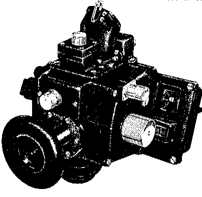
The MA-2 is a hand held bubble sextant for use in aircraft where space will not permit installing an automatic or periscopic sextant. The main body of the sextant, including the controls, averager, and bubble control, are identical to the periscopic sextant. The MA-2, here illustrated, is also provided with a hook for use in astrodomes of older aircraft. The sextant has a field of vision of 12½° and is capable of measuring altitudes from -10° to +92°. The averager provides an average altitude accurate to two minutes of arc over any period of time from 30 seconds to 2 minutes.
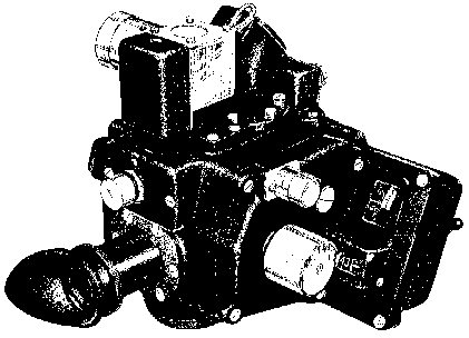
The MA-2 sextant has four main systems: the horizon, the optical, the altitude recording and averaging, and the electrical system. All systems, other than the optical system, are identical to the periscopic sextant. For information on these systems refer to the section on the periscopic sextant.
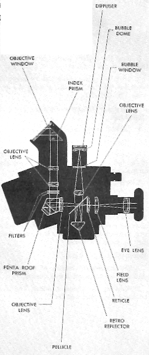
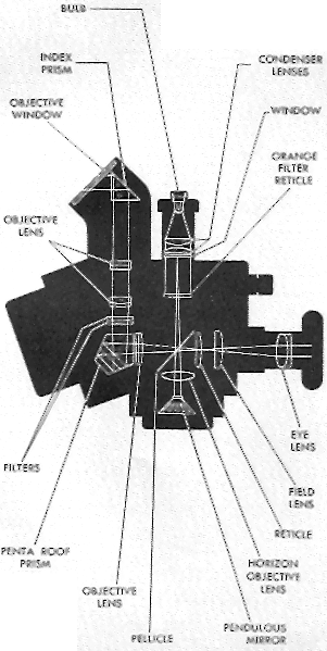
Optical System. Light entering the objective window passes through the index prism, objective lens system, and filters, as shown in accompanying diagram. It is then directed to the eye by a pentaroof fixed prism and forms a real image at the focal plane of the field lens. On the field lens is a reticle, consisting of a vertical and horizontal line, which indicates the center of the field. The focal plane of the eyepiece lens system coincides with that of the field lens and reticle. The eyepiece may be adjusted for focus by rotating the knob directly behind the rubber eyepIece.
Daylight for the illumination of the bubble enters through the diffuser at the top of the bubble chamber. The image of the bubble passes downward through an objective lens and through the pellicle to a retro-reflector. I t is then reflected to the pellicle which in turn reflects it to the focal plane of the main optical system. If the diffuser prevents the entrance of sufficient daylight for the illumination of the bubble, artificial illumination is provided by a 28-volt lamp controlled by a rheostat.
Checking the Sextant. Preflight, inflight, and postflight procedures are identical to those given for the periscopic sextant.
The MA-l sextant, as illustrated, is very similar to the MA-2. The major difference is the artificial horizon system. Where the MA-2 uses the conventional bubble artificial horizon, the MA-l utilizes a pendulous mirror to reflect the image of a horizontal line that is used as an artificial horizon.
As shown in the optics diagram of the MA-l, illumination for the horizon system is supplied by a lamp located at the top of the sextant body. The intensity of the light is controlled by a rheostat on the front of the sextant. Light is projected downward through a condenser lens and a reticle pattern. This pattern is projected through the pellicle and continues to the pendulous mirror chamber. The mirror pattern is reflected back to the pellicle which in turn reflects it to the plane of the main optical system.
Preflight, in-flight, and postflight checking procedures are identical to those given for the periscopic sextant, except for the bubble adjustment.
The material presented in this section dealt with four sextants, the A-l0-A, the A-14 (AN 5851-1), the A-15, and the periscopic (MS 2811). All of these sextants are indirect sighting instruments; that is, observations are made by looking in a horizontal direction and turning an index glass or a prism to bring the body into the field of view.
The A-10-A utilizes a visual averaging device whereby the altitude is selected by choosing the average from a series of marks. The A-14 incorporates a chronometric averaging device, and at the end of a two minute period, the average altitude is indicated on a counter and base scale. With the A-14 collimation must be maintained for a full two minute period. The A-15 sextant is a modification of the A-14 and differs only in the averaging device. The averaging device on the A-15 is a fully integrating variable time deevice. Therefore, average readings may be determined for any amount of time up to two minntes.
The periscopic sextant, in addition to measuring celestial altitudes, can be used to determine true heading and bearing information. The periscopic sextant utilizes an integrater which effects a continuous average over any observation time from 30 seconds up to two minutes. Because it is continuously integrating, it may be stopped at any time up to two minutes as circumstances dictate.
Now let's discuss the matter of checking the accuracy of the observations taken with a sextant.
You can find the index and personal error of a sextant by means of a collimator. The collimator is an instrument which projects parallel light rays at a known angle to the horizontal. Ordinarily, you use the collimator in a horizontal position, adjusting the position accurately with reference to a spirit level. Then the collimator projects light rays parallel to the bubble horizon. Looking into the collimator, you see a cross of light. You place the sextant on a stand facing the end of the collimator and level it with reference to its own bubble. Then, by adjusting the field prism or index mirror, you collimate the cross of light just as you would collimate a star. Since light rays from the cross come to the sextant parallel to the bubble horizon, the cross appears to be on the bubble horizon. Therefore, when the cross and the bubble are in collimation, the altitude scale should read zero. The difference of the reading from zero is the amount of the error. If the scale reads above zero, the error is plus and the correction minus; if it reads below zero, the error is minus and the correction plus. For additional information concerning the collimator refer to Technical Order 05-95C-8.
If you have no collimator, you can check your sextant by observing a celestial body and comparing the observed altitude with the computed altitude for the same time. Sextant error is equal to Hs (corrected for refraction if necessary) minus Hc. To find the computed altitude, of course, you must know your position and the time of the observation. Since a single observation is likely to include some unpredictable personal error, you should find the average sextant error in a series of observations. You can make a good estimate of the scale error of your sextant from about 50 single shots or from about 10 good average observations, of at least 1 minute duration.
Since you must know the Hc of the body from your point of observation, use triple interpolation in HO 249.
Draw up the Hc curve on graph paper using a large scale as explained in the chapter "Celestial Curves." On this same graph paper plot the Hs's and draw through these points a smooth average curve. The vertical distance between the two curves is index and personal error or sextant error. The two cannot be separated and this is the big reason for checking the sextant yourself, since the sextant error as listed contains not only index error but the personal error ofthe individual making the observations. If the Hc curve is above the Hs curve, as it is in the illustration below, the sextant error is minus, and the correction plus. If the Hc curve is below the Hs curve the sextant error is plus and the correction is minus.
Another means of determining sextant error (index and personal) is to observe Polaris from a known latitude. The difference between the latitude obtained by observation of Polaris and your known latitude is the sextant error. (If the Polaris latitude is greater than the known latitude then the error is plus, correction minus. If the Polaris latitude is less than the known latitude then the error is minus, correction plus.) See the chapter "Special Celestial Techniques," for latitude by Polaris.
If you are by the sea or a large lake, you can use the sea horizon as a reference line for checking your sextant. You turn the index mirror or field prism until the sea horizon bisects the bubble; then you read the Hs. After measuring the height of the sextant above the water, you find the dip angle in the table on the back of the Almanac. By looking at the illustration at the right, you can see that you must add the dip angle to the Hs to find the index and personal error. Thus, if there is no error, the Hs is below zero by the amount of the dip angle. If the error is minus, the Hs is still lower; and if the error is plus, the Hs is higher. Suppose that from a height of 15 ft. you observe the sea horizon at an Hs of -0°01′. The dip angle is 4′. Your index and personal error is +3′ and the correction is -3′.
To obtain a bubble-sextant observation, you face toward the body with the eyepiece of the sextant at your eye. Keeping the sextant level by centering the bubble in the field, you bring the body into the field and into collimation by rotating the index glass or field prism.
Collimation is effected when the body is placed squarely in the center of the bubble or horizontally centered alongside the bubble if it is the opaque type. The error will be small if the bubble is anywhere on the vertical line of the bubble chamber field, as long as it does not touch the top or bottom of the bubble chamber field. For greatest accuracy, the bubble should be in the center of this field. The illustration at the right shows examples of proper and improper collimation.
Bubble size affects the accuracy of a sextant observation. The ideal situation is to have a small bubble for ease in determining the center; however, it is also desirable to have a bubble that is active, since too small a bubble is sluggish. Experience has shown that best results can be obtained with a bubble approximately one and a half times the diameter of the sun or moon.
You can become skillful with a sextant only through experience. Practice on the ground is valuable in that the operation of the sextant becomes mechanical but it cannot replace practice in the air. Make good use of available time to take observations even when other forms of navigation are easier and check the accuracy of your celestial by other means. Now let's look at another instrument which is especially important to celestial navigation – the watch.
[from AFM 51-40, Air Navigation, 1955 & 1960]
(last modified 2006-09-10 )